Calculations yielded tension in wires, minimum torque, and time to open
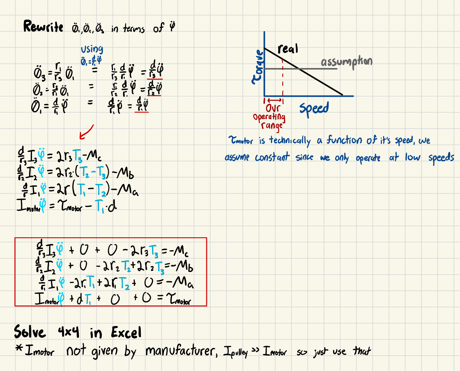
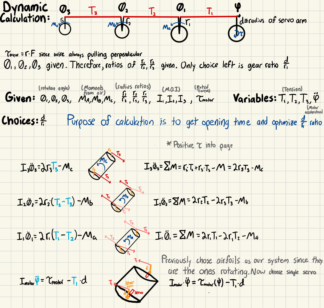
Hand Calculations used to optimize the gear ratio for quickest opening time
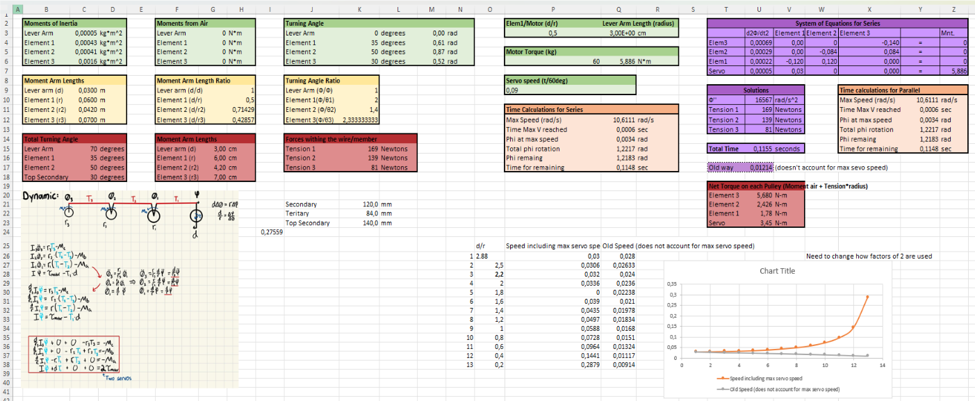
Excel spreadsheet of hand calculations used to optimize the opening time
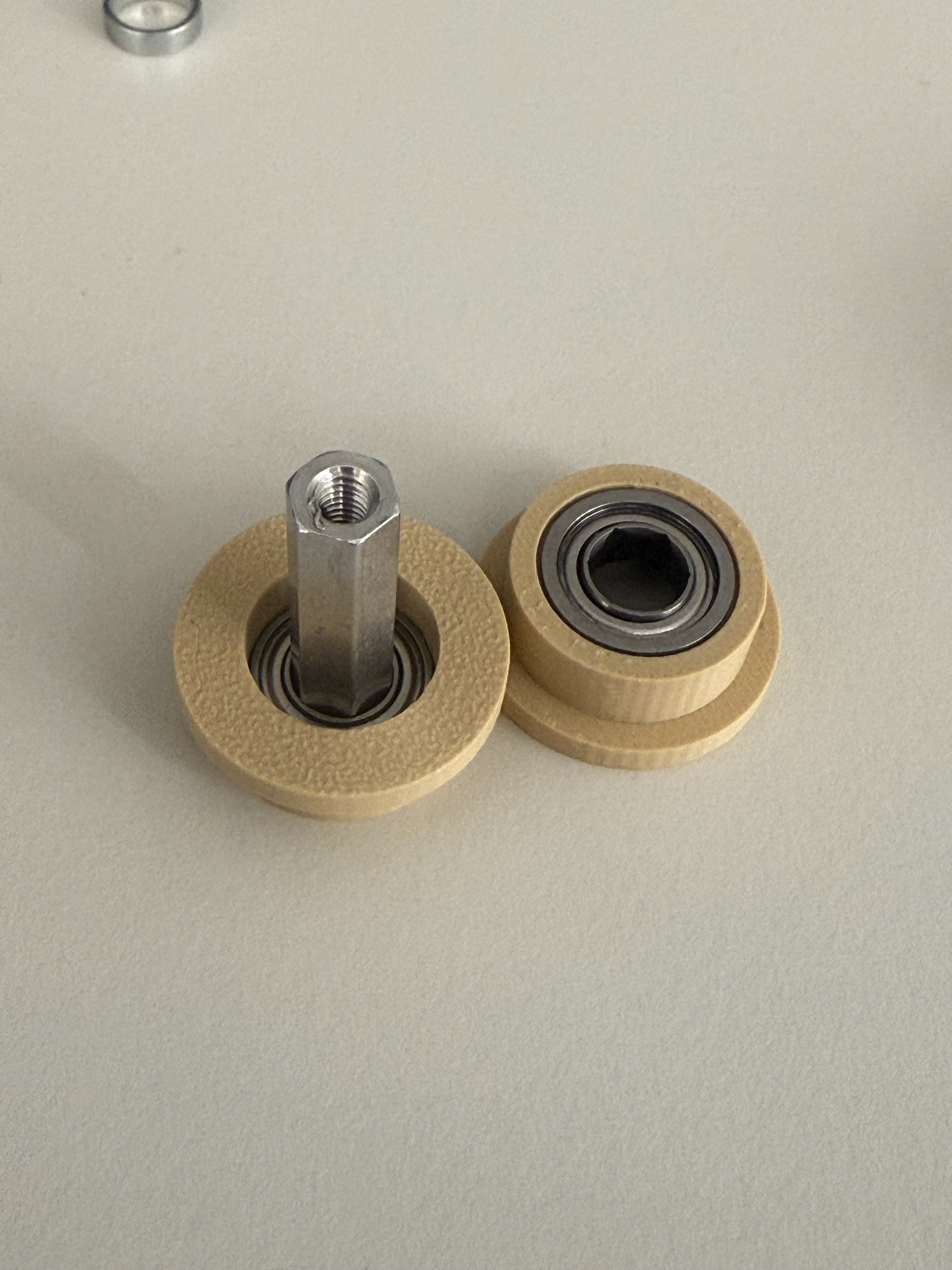
Shaft, Bearing, Insert
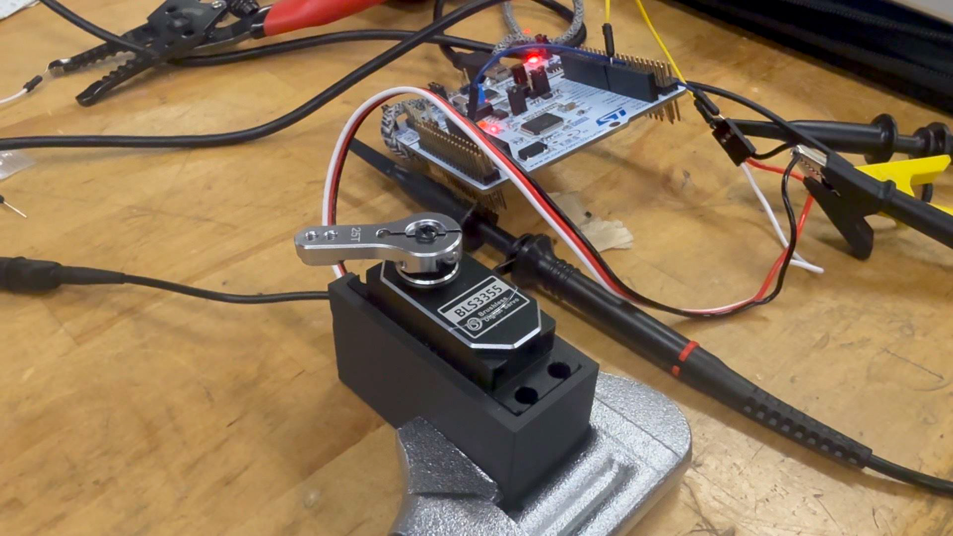
Quick testbed to measure maximum servo torque (Newton meter not pictured)
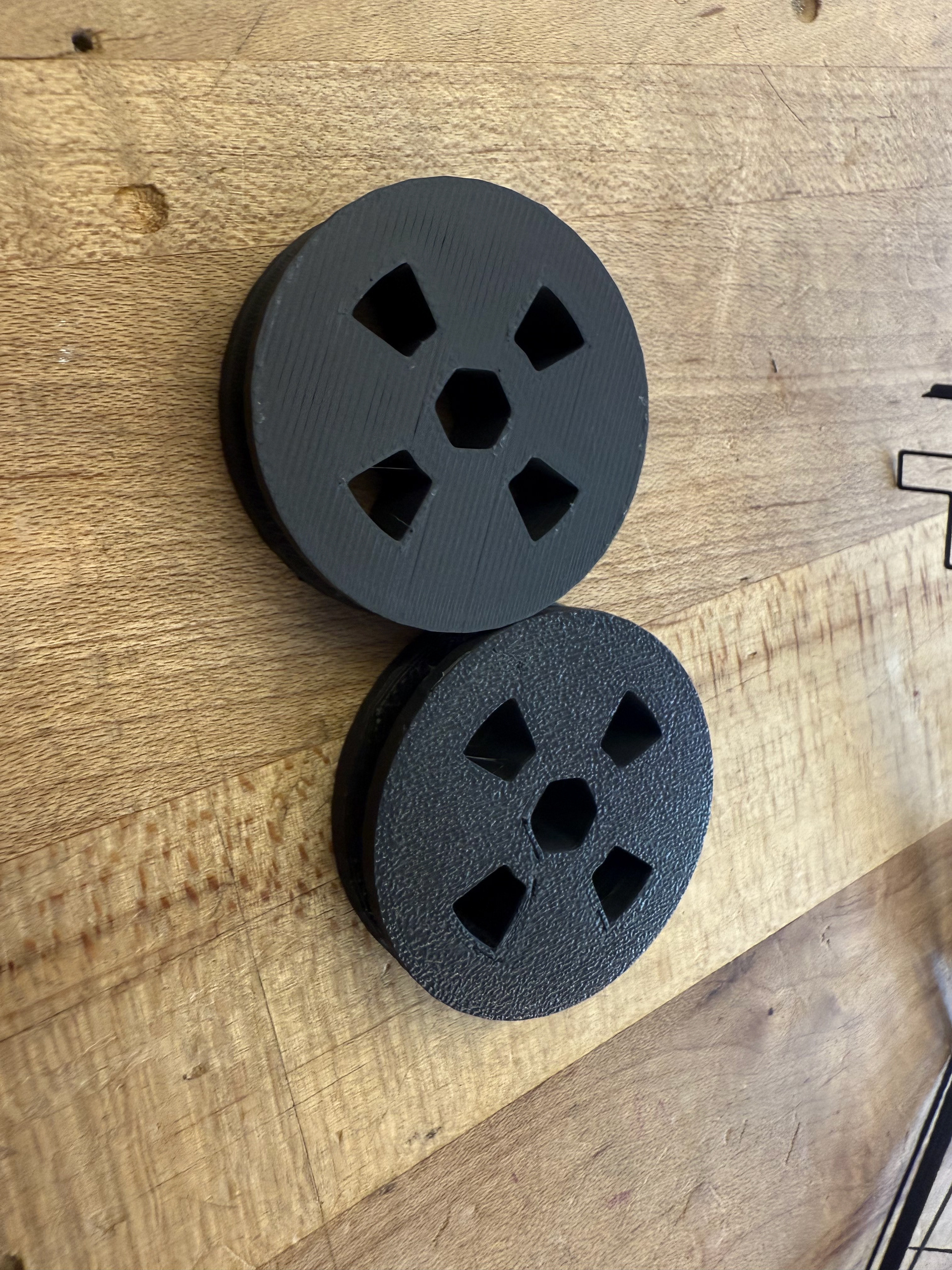
3D-printed pulleys
I led a subteam responsible for completing the Drag Reduction System (DRS), which actuates the rear wing to maximize downforce in corners and minimize drag on straights. While the project progressed in parallel across multiple areas, I oversaw the effort and primarily focused on calculations and design. Other team members contributed through CFD simulations, CAD support, electronics work, and manufacturing.
A key challenge was that the rear wing itself was being designed by another group, which meant that loads and geometry frequently changed. This made it difficult for our subteam to work efficiently, since we could not properly size components until the rear wing design was finalized—something that would not happen for months. To continue making progress, I carried out calculations (see figure above) that ultimately showed we did not need to wait.
The analysis showed that placing the actuation axis at the center of pressure—where aerodynamic torque is zero—would allow the wing elements to open the fastest. While this result may seem somewhat intuitive, it was reassuring to confirm through calculation, especially since we had initially been unsure whether the increased moment of inertia (due to being farther from the center of mass) might negate the benefits of eliminating aerodynamic torque. With a reasonable mass estimate carried over from the previous year, we were then able to calculate the expected loads in the system. This, in turn, enabled us to move forward with selecting and designing the servos, shafts, wires, pulleys, and other critical components without being delayed by ongoing changes to the rear wing design. The calculations also revealed the optimal gear ratio from motor to elements, as well as the estimated opening time based on parameters of the DC motor.
For the failure analysis, we worked by hand with a few simplifying assumptions—for instance, approximating the hexagonal rod as circular with a radius equal to the inner radius of the hex, and treating the motor torque as constant over our small operating window. Based on this analysis, we proceeded to purchase, design, and manufacture all the necessary components. We ran some tests, and I created an assembly plan for how it would be integrated into the rear wing.
Very unfortunately, the rear wing where we would have incorporated our system was not manufactured in time for the competition. We tried to help accelerate progress by assisting with wet layups and mold work, but it ultimately wasn’t enough. Through this experience, I learned that some factors are beyond your direct control, and the best way to mitigate risks is to check in regularly with collaborators to ensure the project is advancing on both ends. I also noticed that the rear-wing team often spent too much time on perfection, which taught me the importance of balancing technical ambition with realistic timelines so that critical features are prioritized and achievable. Otherwise, it’s easy to end up with impressive ideas on paper but nothing that makes it to reality - womp womp womp :(